Solar heater made of beer-cans
Dear Reader,
First of all look at this site, please:
I was inspired by these things which have been found here by
me to build a similar one tentatively. It's a solar collector system
for heating supplement which warms air. It has a quaint feature: it's
built with empty aluminium beer-cans thus while we haven't found a
better name I will mention it as a "beer-collector".
You can read a detailed summary about this theme and steps of
the making on this Hungarian forum:
|
The frame of the collector has been made of
timber, its front has been made of a clear polycarbonate sheet (3 mm,
0.12 inches). The absorber has been made of black-painted beer-cans.
There is rock-wool insulation behind the boxes. There are distributor-collector boxes for the
flowed air at the framework's roof and bottom. These have been made of
aluminum sheets (1 mm, 0.04 inches). The air is streaming through a
filter and a non-return valve from the room to the inlet manifold by a
powerful quiet fan, then the air gets to the tubes made of glued
beer-cans and if the Sun is shining it warms up the air very fast. The
warmed air gets back into the room through the outlet. The room-space,
the inlet manifold, the beer-cans and the outlet generate a closed
system. The air can't escape from the tubes into the frame box else the
inside of the cover gathers dust or mists up. Installed fins at the joins screw the air for a better efficiency. |
 |
First of all I collected empty beer cans. You need to clean
boxes immediately, because those are very fetid. Attention! Beer-cans
are made of aluminum generally, but there are some cans made of iron.
You can test these cans by a small magnet.
When I collected enough cans I drilled each cans below and
above. I used a similar tool which has shown on Picture 1 and 2. Its
diameter is 44 mm, 1.75 inches. Set 45-60 revs per minute. This tool
has an ingredient for the centralization but unnecessary to use that in
this occasion.
 |
 |
 |
|
Picture 1 |
Picture 2 |
Picture 3 |
WARNING! This operation is very
dangerous because walls of the cans are very thin.
Those pieces can provoke any hand injury.
Use a hard plastic ring for own hand protection shown on
Picture 3. This ring has been made by a turner. The ring fits up and
down on the cans. When the drilling was finished the metal sometimes
did not break off. You can use any pliers to take out the fallen
scraps. .
Don't take out the scraps by hand!
Remove the grease from the cans' surface. Any synthetic
stain-remover is suitable for this. Execute this operation outside or
in a well ventilated room.
WARNING! This operation is flammable
and potentially explosive!
The usage of an opened flame and
smoking to be neglected!!
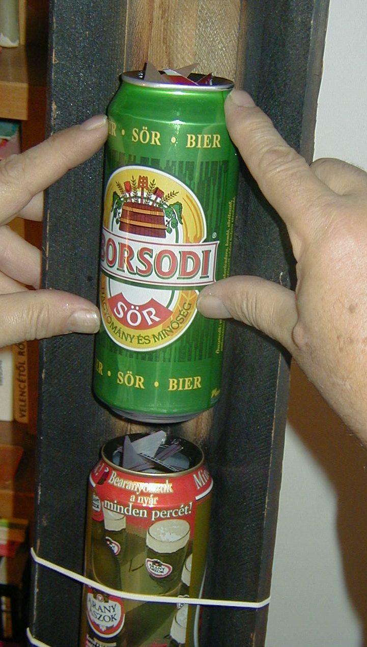
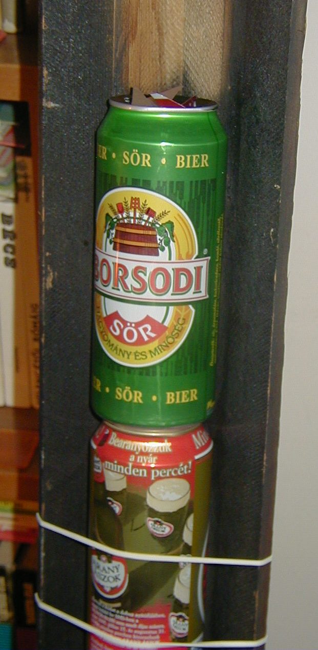
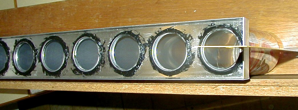
Glue the cans by any heat-resistant adhesive. The adhesive
must be heat resistant at least up to 200 °C. There are
heat-resisting adhesives up to 280 °C or 300 °C too. The roof of
the beer cans and they bottom adjust to each other. If you prepare a
bore with 44 mm diameter, so a little edge stays on the roof. Put some
adhesive onto this part round, and press the bottom of the other box
into it. In this manner the adhesive don't escape from the edge. After
drying the glue will be adequate elastic and stuffed. A detail of the
glued cans is visible on Picture 4.
 |
 |
|
Picture 4 |
Picture 5 |
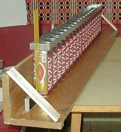
Prepare the trough which has been shown on Picture 8. Make it
from nailed planed timber and the pipes will be straight by this. The
pipes keep in this trough when the adhesive dries. Fasten the cans to
the trough with large fruit rubbers. Hang the rubbers onto the tiny
nails knocked in the rear side of the timber.
The small fins are made of the wispy disk gained from the side of the boxes. Their task to make a turbulent flow in the pipe, so the streaming air cuts more heat from the warmed box wall. Draw it with an alcoholic felt-tip pen, cut it out with a scissors, and then bend it with the help of pliers (Picture 5 and 7). Before gluing it is necessary to make the fins.
The Picture 6 and 10 show the gluing process. The cans glued
together form a pipe. The Picture 11 introduces a pipe, which stays in
the trough, during the drying of adhesive..
 Picture 6 |
 Picture 7 |
 Picture 8 |
 Picture.11 |
 Picture 9 |
 Picture 10 |
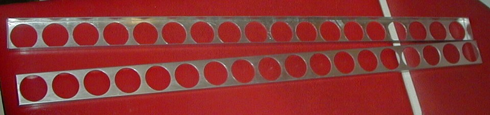
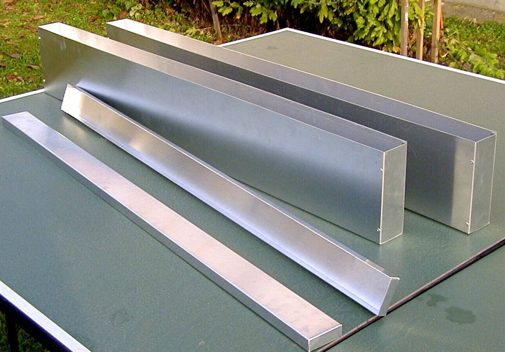
The divisor/collector boxes have built with 1mm aluminum
sheets (Picture 12); the gaps at the edges have been caulked with heat
resistant adhesive. The lids of boxes have cutting with a diameter of
55 mm tool on a stand drill. The pierced roofs are visible on Picture
13. The first row of cans has been glued into the lid of the divisor.
(Picture 14 and 15). The next picture shows the divisor,
collector and the absorber which have been put together before
painting.
The adhesive's drying is very slow. It is necessary to let it dry during at least 24 hours.
 Picture 13 |
 Picture 14 |
 Picture 16 |
 Picture 12 |
||
 Picture 15 |
||
The absorber gets into a box which was made of timber (Picture 17). The reverse side of the box was made of chipboard, for stiffening I developed planks into cassettes. The rock-wool got into these cassettes. These all are covered by thinner chipboard. The installed insulator is visible on Picture 18. Already it has been covered on the opposite part. It is necessary to surround the holes with planks at the inlet and outlet, to fixing the insulation.
 |
 |
|
Picture 17 |
Picture 18 |
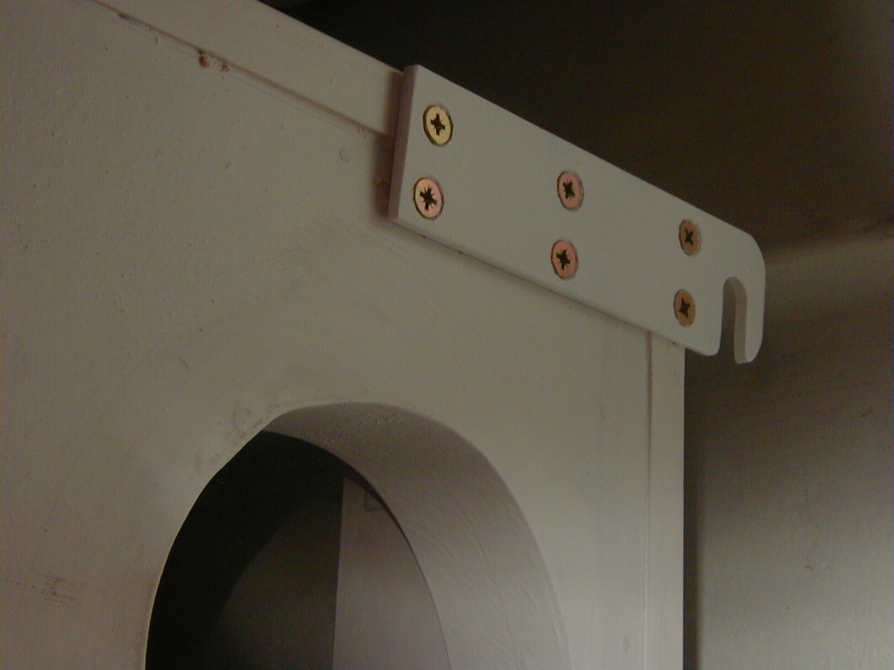
The box got preparatory timber protection, and then I painted
it. I applied four ears onto his four corners to install it to the wall
(Picture 19). I placed the empty frame box to designated place of the
brick-wall. I used 10 mm stem screws for this operation. Finally I
chiselled the brick-wall at the nominated place (Picture 20).
 |
 |
|
Picture 19 |
Picture 20 |
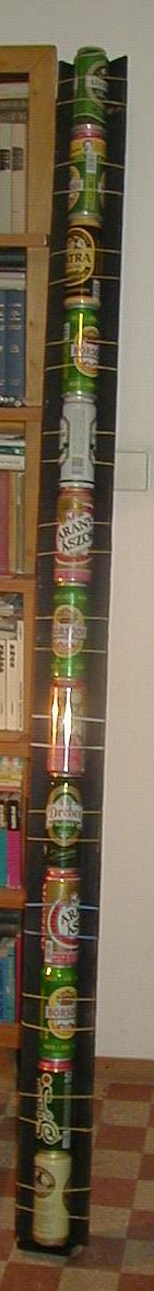
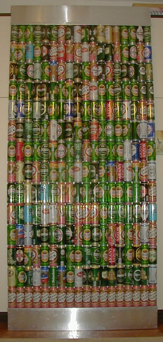
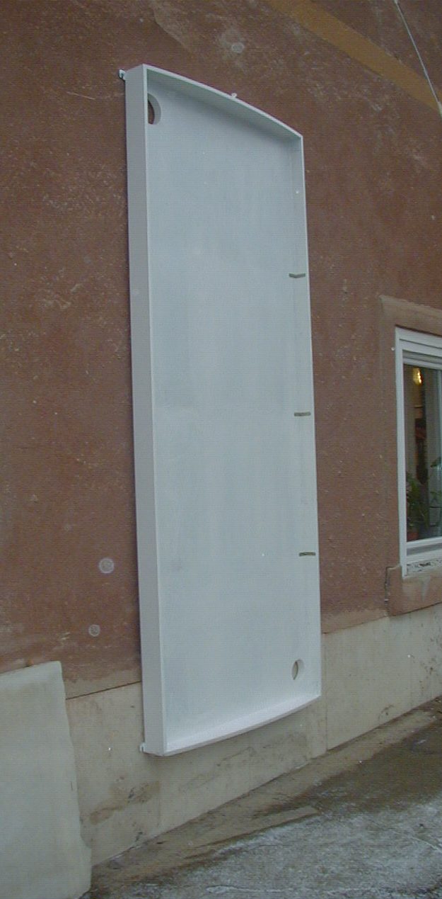
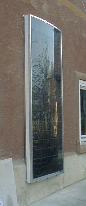
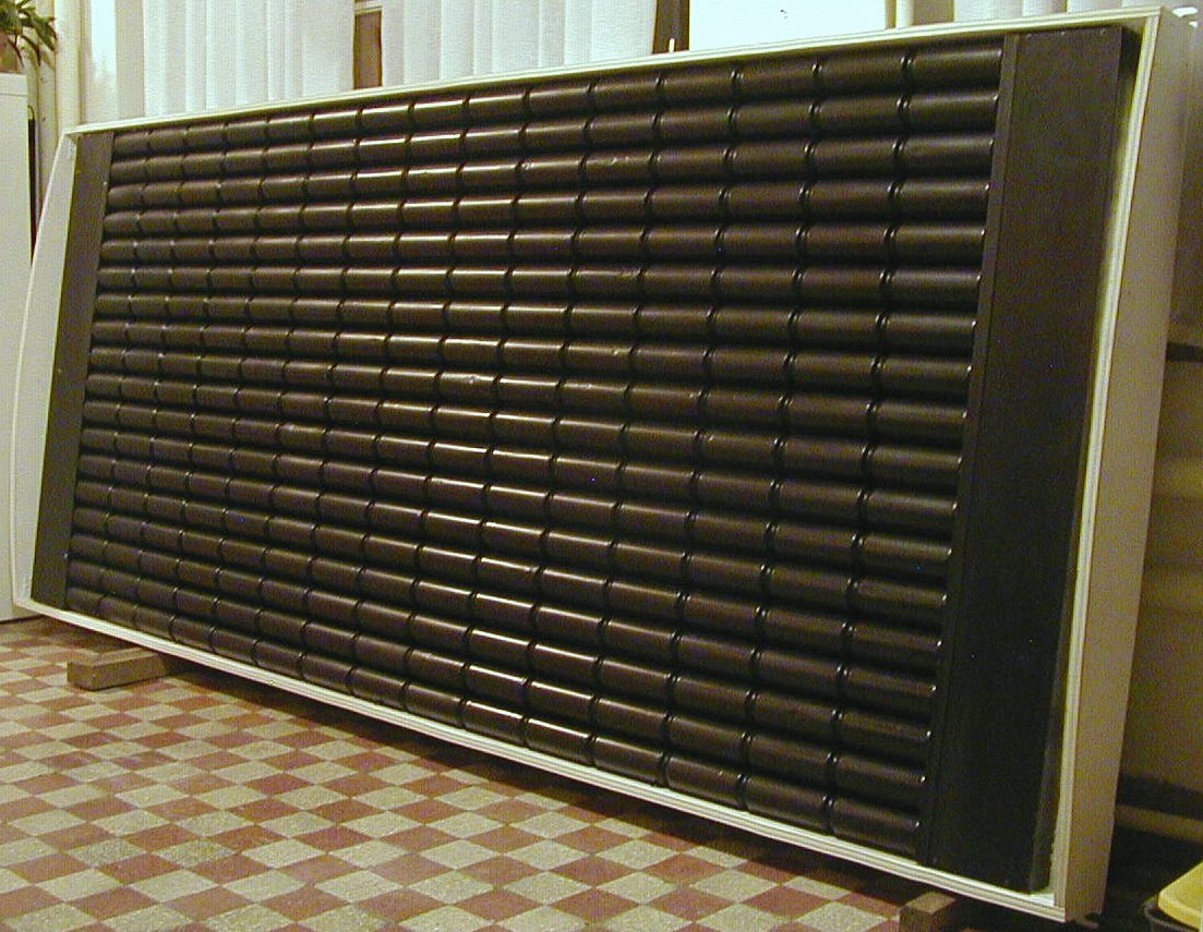
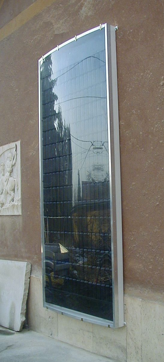
After that the black-painted absorber has got into the frame. The frame got a cover which has been made of polycarbonate sheet. It has been clamped with an aluminum-profile by me.
The polycarbonate sheet is slightly convex, that let him be
more rigid a bit. The installed absorber is visible without cover on
Picture 21. The complete solar heater on the floor is visible on
Picture 22, and the eventually installed heater is visible on the
Picture 23 and 24.
 Picture 23 |
 Picture 21 |
 Picture 24 |
 Picture 22 |
Data:
|
width: |
1238 |
mm |
|
height: |
2966 |
mm |
|
most thickness: |
180 |
mm |
|
full surface: |
3,67 |
m2 |
|
useful surface: |
3,5 |
m2 |
|
weight: |
76 |
kg |
|
inlet diameter: |
100 |
mm |
|
outlet diameter: |
125 |
mm |
|
used cans: |
270 |
pieces |
|
installed fins: |
252 |
pieces |
|
position: |
vertical |
|
This system has a mistake: it isn't capable to store the
produced heat. When the Sun is shining it warms but it is necessary to
utilize the produced heat immediately. If the sun does not shine
inhibit an air flow in him, because it cools the room otherwise. It is
possible to solve it by a non-return valve with minimal heat loss.
A temperature difference switch controls the fan. It is
possible to buy it in electronic shops. It has two sensors. One of
these is installed into the upper effluent tube, the other one is
installed into the lower inlet.
If you set temperatures correctly it will produce about 1-2 kW
of heat energy. It is related to power of the sun.
The collector's dress rehearsal was in the garden before I was
installing him onto his definitive place, on 26 January 2006. It was on
a cloudless winter day, and the sun was radiating strongly. The air was
blown by a little fan, and I measured temperatures with thermometer. A
little anemometer measured the velocity of the air. I defined the mass
flow in the knowledge of the cross-section and I defined the
temperature's difference and then I calculated the power of the heater.
The outside temperature was -3 °C and more than half m3/min of
warmed air was streaming out from the heater. Its temperature was +62
°C. I was calculating from the measured data around 700 watts. If I put
the +/- 5% of tolerance into the rounding error of the displays, even
the 736 W result could have been calculated.
This is precisely 1 horsepower!!!
I wrote about this in the forum, namely in this manner: "...
the beer collector brought a horse from the Sun! It may be it was a
beer-horse! "
The experienced results are promising, the solar heater is suitable for
a heating supplement in sunny time.
(A little explanation to the understanding: The beer-collector
is a
pun, and the beer-horse is a pun too.
The "beer-horse" expression originates from the past when beer was
delivered into the pubs in Europe by carriages towed by horses. These
horses were burly animals, and they have been given a name as
beer-horses by the people.)
|
Implementation, photos 02, March 2006.
|
|